The Plot to Scale feature provides the means to generate hardcopy output of the drawing being measured, the measurements taken and any markups added.
The 'plot' can be of the entire drawing in the current Viewer tab or a user defined part or window of that drawing; it can be at any sheet size supported by the selected output device and it can be at a specific scale or at such a size that it fills the sheet (and therefore is not to scale).
Prior to plotting ensure that any layers, including markup layers, not required are turned off and that the measurements to include are visible.
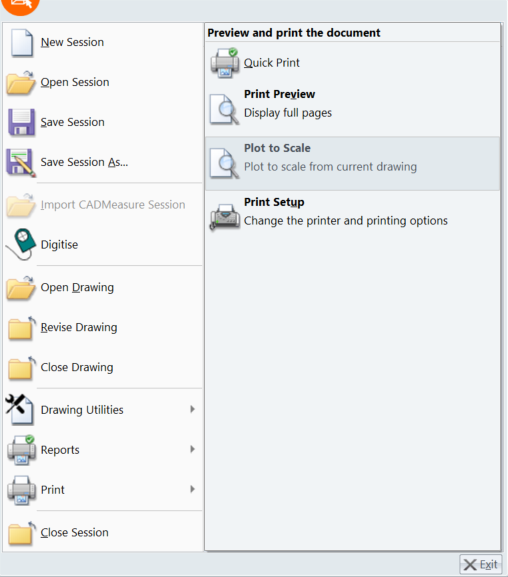
Select Print > Plot to Scale from the File menu.
This will display the Plot to Scale dialog box where the options of what to plot, at what scale, at what size and on what device can be specified.
Click the panels of the Plot to Scale dialog box below to 'jump to' the relevant section in the topic.
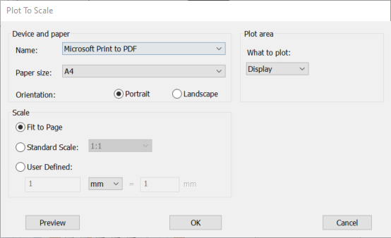
Select the printer or plotter device to plot the drawing out on and also set the size of paper and orientation of the drawing sheet.
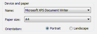
Name drop down list: Select the device (i.e., printer or plotter) to plot the drawing out on. The selection will determine what paper or sheet size options are available. The list will be populated by the operating system with the devices that have been configured for use with the computer. Ensure that the required device is connected and switched on.
Paper Size drop down list: Once the device has been chosen select the size of paper, as supported by the device, to plot the drawing out onto.
Orientation radio buttons: Select either the Portrait or Landscape button depending on how the drawing is to be plotted out.
Select what part of the drawing is to be plotted.
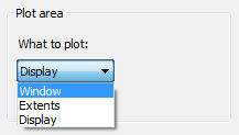
The options in the What to plot drop list are:
· Extents – regardless of what is displayed, plot the entire drawing. Note: This may occasionally lead to some odd results particularly with .dwg files as drawing entities may have inadvertently been placed a long way from their intended location. Use the CADMeasure Viewer toolbar option Zoom Extents to check the drawn extents of the drawing and use the Plot to scale Preview option to check what will be plotted.
· Window – To plot a selected part of the drawing, select Window from the drop down list.
To define the part of drawing to plot, click Window. The Plot to scale dialog box will be temporarily closed so that two diagonally opposite corners can be picked on the drawing to ‘window’ the area to be plotted after which the Plot to scale dialog box will be re-displayed.
· Display – To plot what is currently displayed in the Drawing Viewer
Select the scale to plot the drawing out at.
Select from the radio buttons Fit to Page, Standard Scale, User Defined [Scale]. Depending on the radio button selection made other parametres may have to be set.
· Fit to Page – to plot the drawing so that it is as large as possible on the sheet. Note that the drawing will not be to a specific scale.
· Standard Scale – select a scale from the standard set of scales in the drop down list.
· User Defined – to set a scale that is not on the list of Standard Scales specify the number of drawing units that are to represent 1mm on the plotted drawing. The list of available drawings units are: centimetres (cm), feet (ft), inches (in), metres (m), millimetres (mm) and yards (yd). The default drawing units displayed will be the same as the Drawing Units specified when first opening the drawing or subsequently changed in the Revise Drawing feature.
When select a Standard or User Defined scale you need to take into account the type of drawing being plotted.
· PDF files should already be scaled and therefore the scale to use should be 1:1 to plot at the scale(s) indicated on the drawing. However any scale given in a pdf drawing title block should be treated with great caution as the originator may have simply generated the pdf file issued to you at a ‘print to fit’ using a nominal sheet size (from a measurement point of view this will not have mattered as you specifically scaled the pdf file when opening it in CADMeasure). To plot an indicated 1:50 drawing at 1:100 select a scale factor of 1:2.
· AutoCAD dwg files should be generated and provided to you at ‘real world size’ and so to plot a real size distance of 2500mm so that it is 15mm long on the plotted output, in the User Defined option enter 2500 in the left hand text box, ensure that mm is selected from the drop down list and enter 15 in the right hand edit box. In the majority of cases selecting from the list of Standard Scales will enable you generate plots of your measured drawings.
· DWF(x) files are actually scaled when generated. The difference to pdf files is that scaling properties within the dwf can be detected by BIM or CADMeasure and therefore there is no need to explicitly scale a dwf drawing. In respect of the BIM or CADMeasure Plot to Scale feature, a Scale Factor of 1:1 will generate plots that are in keeping with original hard copy drawings.
For a .dwg file with a line that measures 5000 units and is generated as a .dwf file at a scale of 1:100: In CADMeasure the line is measured as being 5m in length and when plotted at 1:1 it manually scales at 5m at a scale of 1:100; when plotted at 1:2 the line manually scales at 5m at a scale of 1:200 (2.5m at 1:100); when plotted at 2:1 the line manually scales at 5m at a scale of 1:50 (10m at 1:100).
Prior to outpting on utthe selected device it is strongly recommended that you use the Preview function to check the appearance.
To preview, on screen, how the drawing will appear for all the parametres set, click Preview.
The drawing is displayed in Plot Preview screen.
If the drawing does not appear as it is required then click Close on the ribbon.
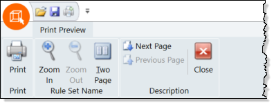
In the Plot to Scale dialog box make any adjustments as necessary and check again using the Preview option.
If the drawing preview is suitable then either click Print or Close on the Print Preview tab of the ribbon and then click OK in the Plot to Scale dialog box..
To plot the drawing using the parameters set, click OK.
To abort the Plot to Scale operation, click Cancel.