The Markup features within CADMeasure enable the addition of line work, shapes, revision clouds, notes, selects etc. without affecting the underlying drawing. These Markups can be used for any purpose such as areas of work, phasing, raising queries, noting assumptions made, indicating areas where measurement is complete.
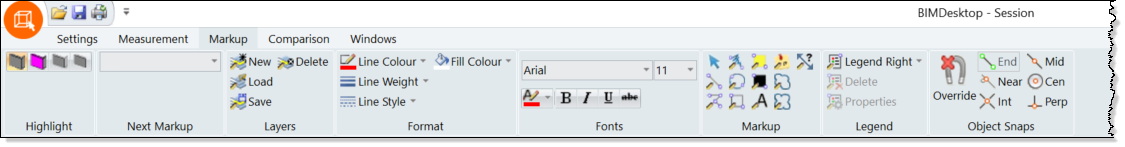
The Markup tab contains the options to add Markups and set their default appearance.
Also, see Markups Window and Properties Panel.
Click the panels of the markup ribbon below to 'jump to' the relevant section in the help guide.
Set the layer on which all subsequent Markups are to be placed. Select the layer from the drop down list.
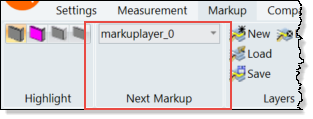
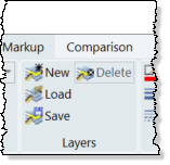
The management of layers used for the marking up of drawings
Option |
Icon |
Description |
New |
|
Create a new Markup objects layer |
Load |
|
Load a layer & associated Markups previously saved in an external .hsf file. Use this option to load Markup files from Causeway Viewer into CADMeasure. |
Save |
|
Save the current layer & Markups to an external hsf file. This file can be loaded into Causeway Viewer. |
Delete |
|
Delete the current layer and all associated Markups |
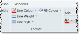
The selections made in this panel set the defaults for Markup line work and Markups that use a background colour .
Exclusions:
1. Line Weight and Line Style do not apply to Annotate (Post-it) Markups
2. Fill Colour does not apply to Highlight and Redact Markups
Option |
Icon |
Description |
Line Colour |
|
Set the default line colour for Markup line work |
Line Weight |
|
Set the default line thickness for Markup line work |
Line Style |
|
Set the default line style (for example, solid or various types of dashed line) for Markup line work. |
Fill Colour |
|
Set the default fill colour for the circle, rectangular and Annotate (Post-it) Markups. |
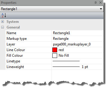
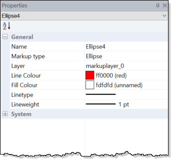
To change any these properties once a markup has been placed, select the markup on the drawing or in the Markups Window tree, this will enable the Properties panel and properties can be changed as required.
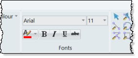
The selections made in this panel set the defaults for Markups that use text.
Option |
Button or Field |
Description |
Font Name |
|
Set the default text font for any markup text. Select from the drop down list of text fonts available on the system. |
Font Point Size |
|
Set the default height (using point size) of any markup text. Select from the drop down list of point sizes for the selected font or type in a 'user defined' point size. |
Font Colour |
|
Set the default colour for any markup text. Select from the palette of colours presented. |
Bold enable/disable |
|
Toggle OFF or ON emboldening of Markup text |
Italic enable/disable |
|
Toggle OFF or ON italicisation of Markup text |
Underline enable/disable |
|
Toggle OFF or ON underlining of Markup text |
Strikeout enabled/disable |
|
Toggle OFF or ON strikethrough of Markup text. |
To change any of these text properties once a markup has been placed, select the markup on the drawing or in the Markups Window tree, this will enable the Properties panel and properties can be changed as required.
Commands to insert Markups.
When a Markup command is in operation most of the options on the Markup tab will be disabled.
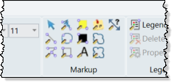
Click the buttons for details
· Line
· Polyline
· Ellipse
· Redact
· Text
· Cloud